|
| Oriel Chambers, 14 Water Street Liverpool. Peter Ellis 1864 |
Back to oldies. In October 2012 I was invited to an architectural seminar in Liverpool, organized by
Tile of Spain, to discuss about ceramics in facades. Another speaker was Maurits Van der Staay, an associate in
Renzo Piano Building Workshop, who presented their terracotta façade on
Central St Giles London. The morning after the venue Maurits and I re-visited two architectural jewels in Liverpool: Oriel Chambers in 14th Water Street (1864) and a similar office building in 16th Cook Street (1866). This post will remind us about these two buildings and their now forgotten architect; and in particular how they deserve credit as some of the first examples of a lightweight glazed façade – a real curtain wall – installed in a multistory building. Please take note of the dates again, 1864 and 1866: that means only thirteen years after the Crystal Palace and thirty years before the design of pioneering Chicago School facades as the Reliance or the Fair Store. Real oldies, right?
 |
16 Cook Street Liverpool. Peter Ellis 1866.
(Image from Maurits van der Staay 2012) |
The
Wikipedia entry for curtain wall has two images of Oriel Chambers and 16 Cook Street, and it refers to them as two of the world's first buildings to include a curtain wall façade. By this they mean a fairly glazed multi-storey building set in an urban context; not a warehouse, a dockyard or the gable of a large train station. Let’s reckon from the start the impossibility of determining what the real ‘first’ curtain wall was, since the development of any building system is an evolutionary process moving through several directions simultaneously. But it’s time to give Peter Ellis, the architect of Oriel Chambers and 16 Cook Street, the merit he deserves as one of the pioneers in curtain walling, regardless the fact that his influence was small, if any.
The available literature on these two buildings is scarce. It is clear that their author was
Peter Ellis (1804-1884), a local architect and surveyor about whose life and work there are strong shadows. These are the only two buildings clearly attributed to him; we don’t know if Ellis signed any other project in Liverpool or anywhere else. There are no records of his previous and later activities: he may have been a surveyor, a civil engineer, or a developer before designing Oriel Chambers and 16 Cook Street; and apparently he went back to surveying or to other businesses after finishing the second building in 1866. The reason seems to be found in the fierce critics with which the two buildings were received at the time, but we will come back later to that.
 |
| Oriel Chambers among its neighbours facing Water Street |
 |
| Oriels and stone: it's not all glass! |
Both buildings have been designed with the same purpose: office space for rent in the shape of chambers. A
chamber is what the Americans would call
suite, that is, a small office valid for any purpose; whether legal, financial or commercial in general. Each chamber was supposed to be rented for a private business with a small number of users, between two and ten generally. There is little space for sumptuosity, and above all no plan space to be lost in halls or extra money to be devoted to architectural features on the façades.
The Oriel Chambers building
It seems that Peter Ellis won the commission for the first building (Oriel Chambers) as a result of a competition between local architects organized by the developer (an unknown T.A., as the golden initials on top of the main façade declare). The reasons for selecting Ellis’ scheme – from a developer’s perspective - are clear by having a look at the plans and sections. The entrance to the building is located out of the main façade axis because it fronts the corridor, which is located at the axis of the inner part of the building, much longer than the Water Street façade. In other words, internal space efficiency is given much more importance than architectural expression.
 |
| Oriel Chambers: Ground floor plan and elevation to Covent Garden St |
 |
| Oriel Chambers: Elevation to Water St, section and elevation to the inner courtyard |
The building from the outside seems to have three main floors but in fact there are five, all with a large amount of natural light and free available space. The central corridor separates the plan in two lettable areas per floor: one side opening to Covent Garden Street and the other side opening to a narrow internal courtyard. Covent Garden Street was not too wide even by 19th century Liverpool standards, so not much light would be expected from the street. But the bit facing the courtyard would be much darker than the other, resulting in a potential loss in let revenues. So a scheme providing lots of light to both sides of the building (external and courtyard’s façade) must have sounded appealing to the owner. And the was right in his selection: the building is still
a lettable space today and it houses the same kind of small firms (barristers among others) with apparent success almost 150 years after it opened.
 |
Oriel Chambers: proposed occupation in a typical office floor.
The courtyard is the narrow strip located above to the centre-right.
|
 |
Prior Bolton's oriel window at St Bartholomew
the Great church, London c. 1500.
It's interesting to note that the church
was being restored during the 1860s... |
Oriel Chambers was named this way because of the
oriel (projecting bay) windows that cover in vertical stripes the two facades. The short façade, seven stripes of windows with the non-symmetrical main entrance, opens to Water Street with a southeast orientation. Water Street was one of the important arteries of the city at the mid-nineteenth century, connecting the City Hall with the Mersey river docks. The lateral northeast façade to Covent Garden Street was by far the largest, extending originally along 20 window strips, divided in five sectors of four vertical bands each. The back half of the building was damaged by German bombs drop over Liverpool during the Second World War, so that now only the first 12 strips are original, and the rest of the volume has been rebuilt in a different style by James & Bywaters in 1959. In fact, the wartime damage enabled the original construction to be fully appreciated regarding its architectural and engineering significance.
 |
| Oriels facing Water St. |
The original structure is a combination of cast iron H-shaped columns forming a grid frame with cast iron inverted T-section beams (girders), spanning along the short direction of the building. The shape of the girders comes
from other sources; I have verified the columns section on site and they remain as originally. Lateral stiffness is provided by transversal brick walls with chimneys that interrupt the long volume every four stripes. The span between frames is small and it coincides with the windows’ module. This means that the external and internal facades (opening to a large but narrow courtyard) become free of any structural stiffening requirement.
 |
| Oriels facing Covent Garden St. The slim stone column is cladding a cast iron H-shape stanchion. |
And here is where Peter Ellis started making his magic. The external façades facing Water St and Covent Garden St are covered with oriels: bow windows with an overhang bottom support. Oriels facing Covent Garden St are wider than those facing Water St (see image below); which seems a good idea since the former receive less natural light. The column line between oriels is externally clad with a thin section of stone pieces, reminding slender Gothic columns. These lines don’t end up in arches though, but instead finish rather abruptly – one would say in an abstract way – when they reach the top of the building line. For us the visual result isn’t striking: we are used to building facades resembling rectangular grids. But for Ellis’ contemporaries this façade must have been a clear break in relation to what was considered ‘proper urban architecture’.
 |
| Oriel width comparison: left to Water St.; right to Covent Garden St. |
The lightness achieved through the oriels is really high by today's standards, and it must have seemed extraordinary to Ellis' contemporaries. The first two images below are inner views of office space overlooking Covent Garden St, and the last one is an image of a narrower window located at the ground floor, with views to Water St.
 |
| View of the oriels from inside. Façade overlooking Covent Garden St. |
 |
| Same as above |
 |
| View from an oriel towards Water St. |
Air ventilation is obtained via one side-hung window at every oriel. The height of the window is 1/2 the height of the oriel, so they can be read as vertical sliding openings, which they are not. The sash opens to the inside and the sash retainer is visible from the outside. See details here below.
 |
| Side hung window, opening to the inside. Notice the bottom hinge. |
 |
| Sash retainer located outside the window. The sash can be locked in three positions. |
The (hidden) curtail wall in Oriel Chambers
Now, glazed as it looks, how could this be the first curtain wall in a multi-storey building in history? This is not the case if you focus on the external facades only: the amount of glass is noticeable but what we see is a continuum of large projecting glass elements in a rectangular grid of stone blocks cladding an iron frame.
There is at least a previous building in Glasgow that could claim precedent, the
Gardner’s Warehouse in 36 Jamaica Street (see below), built in 1856 by John Baird using a structural system patented by R. McConnell, iron founder. The Gardner’s façade reminds the Crystal Palace, built in London in 1851, in a more direct way than Peter Ellis’ one. The building in Glasgow was a warehouse after all, ours is an office building located in prime location in Liverpool.
 |
| Gardner's Warehouse. 36 Jamaica St, Glasgow. John Baird 1856. |
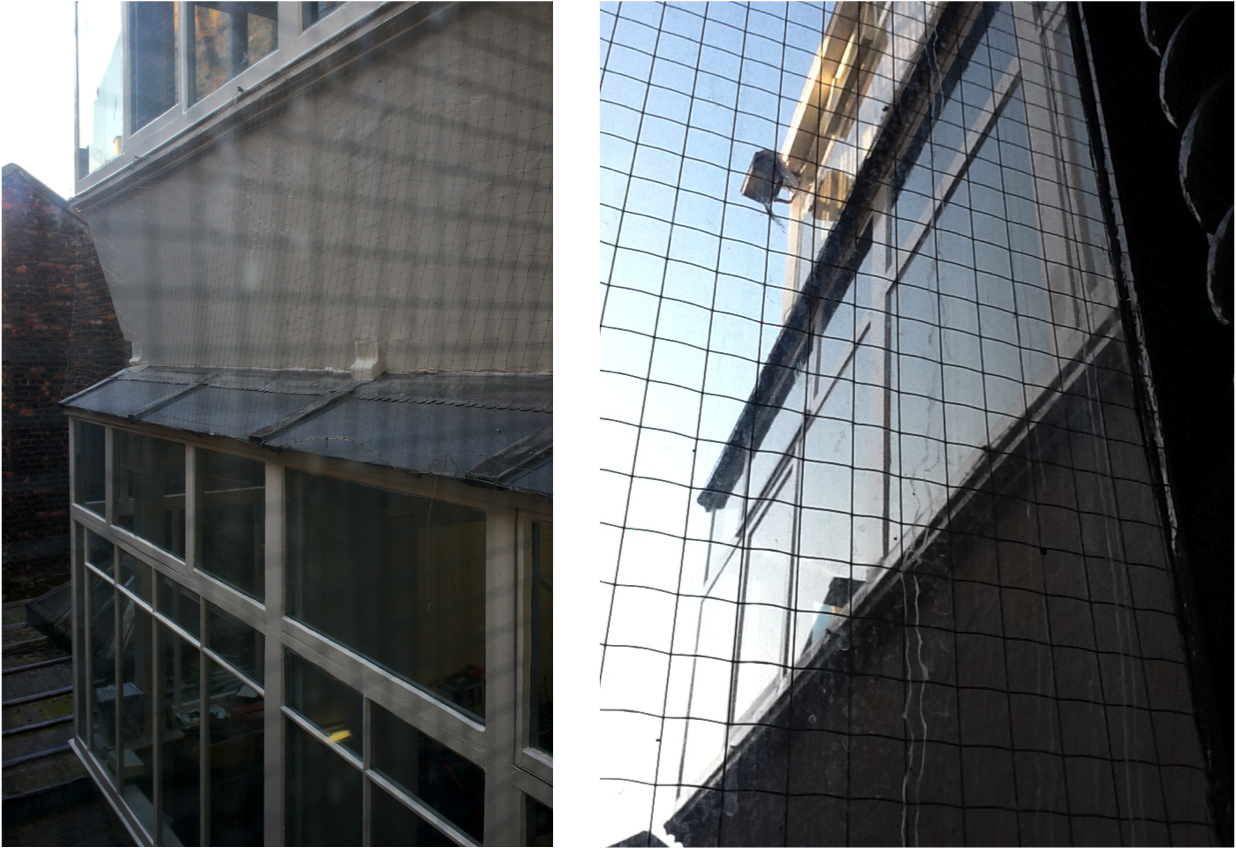
The real secret of Oriel Chambers is hidden behind; at it becomes visible only when you are given access to the inner courtyard. My colleague Maurits and I were lucky to arrive to the building on a workday morning at 9am, when clerks were entering their offices. Looking like an architect has advantages if you want to access a private property, and we were soon taken to the courtyard through the solicitor’s firm occupying the main floor.
There came the surprise: a receding, all-glass façade with a shape of protruding elements between columns seemed to absorb any little ray of light arriving to the courtyard. Again, an architectural solution that seems contemporary to us but absolutely new at the time of its design. One may say that the oriel glass boxes at the front are the ‘culturized’ version of this completely ‘form follows function’ glazed solution at the back.
 |
| Left: view of Oriel Chambers inner courtyard. Right: vertical section of the curtain wall opening to the courtyard. Notice the cast iron vertical stanchion and how the curtain wall moves out of it every floor down. |
Look at the vertical section above right and you will get it: each floor recedes a bit over the one below to allow for more light coming to the bottom. The sloped rooftop piece above the windows at each level is made of wired glass to obtain direct solar radiation. A counter-sloped panel acts as bottom parapet, and it looks like a thin piece of timber with an external bituminous layer. The iron H-shaped columns are not at the receding façade line but in a vertical axis independent from it. The glazed wall acts as a thin, lightweight layer gently cladding a structure, not taking any load but its own, with a shape that bows to light and brings it in without losing a bit. That's a mature curtain wall in concept.
Since there are very few images of this extraordinary piece or architecture in the Web, I am adding here below a selection of the pictures I took during our early morning visit.
 |
| General view of the courtyard. All structural members of the curtain wall are in timber. |
 |
| The top and vertical members are in glass; the bottom one is a timber panel. |
 |
| Detail of the curtain wall, floors one to three (4th floor is flat vertical) |
 |
| Contrast between the curtain wall and the receding structural wall to the left. |
 |
| Corner of the curtain wall at the edge of the courtyard. The narrow strip is located opposite to Water St. |
 |
| Corner of the curtain wall looking up. Note the receding structural wall in the centre. |
 |
| Connection between the curtain wall and the receding brick wall. The building to the left is the bombarded wing that was re-built after the war. |
 |
| Detail of the above. The sloped glass on top is very visible. |
 |
| View of the curtain wall to the courtyard from inside. See the sloped glass on top. |
This is clearly a proto-20th century office building curtain wall, thirty years older than those of the Chicago School but going far beyond them and connecting directly with Gropius’ Fagus Factory in Alfeld – which was to be built fifty years later! Now is when you grasp the importance of this hidden place.
16 Cook Street – more news to come
After the successful visit to Oriels Chambers Maurits and I walked to Cook Street, located less than ten minutes away, also at the city centre. 16 Cook Street is another rental office building, smaller than the previous one, that Peter Ellis finished in 1866. I have not found any information about the owner. Was it the same developer from Water Street or a different one? Was this building the result of a competition or a direct commission? Judging by its smaller dimensions and the use of very similar architectural features I tend to think that this was a direct commission, for a client who knew well what he wanted.
The building plan is an L-shape (as Oriel Chambers) but much smaller in size and with only a main façade. The rear and lateral walls open to a courtyard that was as narrow as the former.
 |
| 16 Cook Street, top of front view |
 |
| Contrast with contemporary neightbour facade |
Again, you can find some references in today's architectural literature to the main façade but very few to the rear one. The façade to Cook St is perfectly symmetrical. The play between glass and stone appears again, but here there are no oriels: glass remains flat between slender stone-clad columns. The whole can be read as an abstract gothic- or Venetian-like window: a central, three-strips bay ends in an arch at the top and is flanked by two smaller vertical bays, also ending in smaller arches. The building, as that in Water St, has five floors, but here all floors are fairly the same height and express themselves similarly to the façade. Verticality together with light-catching seems to be the theme for Peter Ellis here.
The entrance to the building is located at the left corner, with the shop entrance conveniently symmetrical at the right end. The entrance hall is a slender corridor connecting the street with a spiral staircase that opens to the back courtyard, clad almost entirely in glass with the thinnest of cast iron mullions.
 |
| 16 Cook St: back elevation (left) and spiral stairs from the courtyard (right) |
 |
| Spiral stair from inside |
The stair and its cladding are supported from both sides at every floor, leaving the impression that the whole is floating without any column. Clever but not so difficult considering its tiny dimensions. This leaves the rest of the plan available for one or two offices per floor, with plenty of light entering through the street and/or the rear courtyard windows.
 |
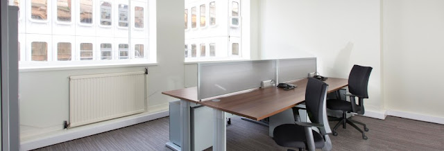
| The façade as seen from ABW Architects office |
Maurits and I were lucky once again. The second floor is at present occupied by
ABW Architects, a firm formed in 2008 by two partners, Simon Almond and Andrew Brown, working across the northwest UK. We were given access to their studio and could have a chat and take pictures. The atmosphere inside was great – lots of light but definitely a small space. Old Peter Ellis was clever enough to conceal the limited available space playing with a continuous volume that seems much larger from the street.
 |
| Drawing from inside the office (from ABW Architects webpage) |
And again a curtain wall surprise was waiting for us there. It was not visible in the front façade, glazed as it is. Only when you access the office floors you perceive the small courtyard and the way the building opens to it at the back in search of light.
 |
| Back curtain wall as seen from the stairs |
Here the façade to the courtyard is not receding back as it moves up, probably because of the lack of space. But we find again the lightweight, protruding curtain wall in three planes: vertical and sloped with glass, counter sloped with a timber panel. And this time the curtain wall ends in a transparent corner at the very back of the building.
We saw two H-shaped columns completely independent from the wall. One of them shows how the curtain wall is attached to the cast iron structure using an iron strip in tension (see bottom image left).
 |
| Inner cast iron column at the back office and curtain wall connection |
 |
| Corner glass around cast iron column |
The other column at the back corner is even more striking, because the glass wall completely clads the column from the outside without touching the structure. We have seen this detail many times in modern curtain wall architecture, but in 1866?
The contact of the curtain wall horizontal stripes with the vertical glazed cylindrical staircase takes place in a clean way. It could be a Dutch architectural detail from the 1930s. An amazing solution but concealed from everyone’s view – as much today as when it was built.
 |
| Details of the curtain wall around the corner cast iron column |
Reaction to the two Ellis’ buildings
Seen from today’s perspective Oriel Chambers and 16 Cook Street may be seen as a precedent and even a paradigm of the Modern Movement - but it was not one immediately appreciated to say the least. Oriel Chambers was seen, for the local Porcupine, as ‘hard, liney, and meagre’. The strongest critic by far came from the London architectural periodical The Building News in February 7, 1868, signed by a ‘our own correspondent’. The critic pompously dismissed Oriel Chambers out of hand:
This is a kind of greenhouse architecture run mad; consisting of a series of vertical bays running completely from top to bottom of the building (…) rising from the plinth without any basis, said shafts being flanked by a very large coarse “nail head” ornament. (…) The style, in short, might be described as “lunar Gothic;” and no one who has not seen it would believe, we think, that such a thing could, in the present day, be erected in cold blood by any person calling himself a member of the architectural profession.
In a similar vein, The Builder stated:
The plainest brick warehouse in town is infinitely superior as a building to that meager agglomeration of protruding plate-glass bubbles in Water Street termed Oriel Chambers. Did we not see this vast abortion (which would be depressing were it not ludicrous) with our own eyes; we should have doubted the possibility of its existence. Where and in what are their beauties supposed to lie?
As late as 1921, Charles Reilly, head of the Liverpool School of Architecture, called it the ‘oddest building in Liverpool, at once so logical and so disagreeable … as a cellular habitation for the human insect is a distinct asset to the town’.
 |
| Oriel Chambers' glass windows protected during the Second World War |
It is clear now that those radical cast iron frames that Glasgow, Manchester, and Liverpool produced among others in the 1860s and 70s, led after the 1870s to a slow falling-away from industrial innovation and to a shift back to London-supported historicist decorations. Probably this was the origin not only to the decline of the North but also to British near-absence from the Modern Movement up to very late in the twentieth century.
The positive reaction produced by the two Ellis' buildings, although little, was not completely inexistent in 20th century British architecture. As Brian Hutton wrote in Architectural Review in 2008:
Perhaps Oriel displeased locals because it abstracted from a Gothic model in a city that remained mostly Classical. (…) And indeed, to eyes now less Modern than Post-Modern, what may strike from the Oriel is less a paradigm of rationality than something both more abstract and more wilful. So that when, in the 1960s, James Stirling drew from Oriel in his Leicester Engineering Laboratory, his model was neither its chamfered details nor even its functionalism, but the geometric glass cascade of its atrium walls.
James Stirling, although born in Glasgow, grew up in Liverpool and studied architecture there.
Adam Caruso (from Caruso St John) is a contemporary architect with a strong personal link to the two Ellis buildings.
He wrote in 2010:
I’m not so interested in the Ellis buildings being examples of a proto-modernism, a part of that inexorable linear progression from the Crystal Palace to European inter-war modernism. I think that’s a convenient post-rationalisation perpetuated by modernist historians. I am more interested in the Ellis buildings in the context of the cast-iron offices and warehouses that were being built in the mid-19th century in Liverpool and Glasgow, like the Gardner’s Warehouse in Glasgow by John Baird in 1856. These buildings had cast-iron structures and facades and had all but eliminated most of the elements of what would have previously constituted a “correct” urban facade. I am particularly interested in why Peter Ellis chose to clad his cast-iron structures in stone,organised according to a Gothic language (…). He was developing an expression for his building that was in addition to, and was autonomous of, their technology.
Peter Ellis, John Root and curtain walls
Can we spot an influence of Peter Ellis’ two proto-modern curtain walls in any later period of architecture? As Adam Caruso mentioned above, it is almost impossible to trace any linear progression from the Crystal Palace to the glazed boxes of the 1930s passing through Peter Ellis. A potential link might be the application of glass and iron frame technology to the front of urban buildings, almost for the first time in history. But many years had to pass before large glass plates and iron / steel frames could come back to the front.
An interesting side influence, though not too obvious, has been established between our two buildings and the architectural training of John Wellborn Root (1850 – 1891), who would become the partner in the Chicagoan firm Burnham & Root, one of the founders of the Chicago School around the 1880s and 90s. Root was born in Georgia and raised in Atlanta with his parents. In 1864, when Atlanta fell to the Union during the American Civil War, Root’s father managed to send him with two brothers on a steamer to Liverpool, where John’s father had shipping business contacts. While in Liverpool, Root studied at a school in Claremont for three years (from 14 to 17 years old), and he even passed the exams for entering Oxford. But in 1867 he returned to the US to study architecture at New York University.
It can only be a speculation, but a teen-aged John Root might have seen and remembered the brand new Oriel Chambers in Liverpool, together with the spiral staircase of 16 Cook St, the latter finished just months before he sailed back to America. Now fast forward to the 10 floor-high Rookery building in Chicago, built in 1888, one of Root’s masterpieces. Can you see a vague influence from Oriel at the top corner stone pinnacles?
 |
| The Rookery Building Chicago, 1888. Burnham and Root architects. |
There are no oriel windows here, except maybe the gentle curvature of the central bay of windows up to the sixth floor...
 |
| The Rookery building Chicago, 1888. Spiral staircase at the inner atrium |
Perhaps the clearest reminiscence, once again, does not take place at the front but in the courtyard above the glazed atrium. Here yes, the spiral staircase in the centre is in a similar vein to Ellis’ model in Cook Street, and the window-to-wall ratio of the inner façades reminds that of the two courtyards back in Liverpool.
 |
| Engraved plate at the door of Oriel Chambers |
What happened with Peter Ellis after his two office buildings were finished (and received with derision in Liverpool and London)? We have no idea: he seems to have come back to surveying or to civil engineering, but there are no traces of his activities at all. There are no buildings signed by Ellis after 1866, so it seems quite obvious that the sharp criticism ended with his short architectural career. The last news is that of his death in 1884, at the long age of 80 years. His obituary appeared in the Liverpool Daily Post in October 21.
It is an irony to see that Peter Ellis is remembered (in a stone engraved plate by the door to Oriel Chambers, see above) as a '
pioneer in the use of prefabricated structural units in cast iron'. This, being true, is unfair to his evident contribution as a forefather of curtain walling, clearly his largest achievement and the one by which he is and will be remembered. Sometimes two buildings are enough to have your name written in history.